HAROLD
Full-Scale Bogie Rolling Contact, Adhesion and Braking Rig
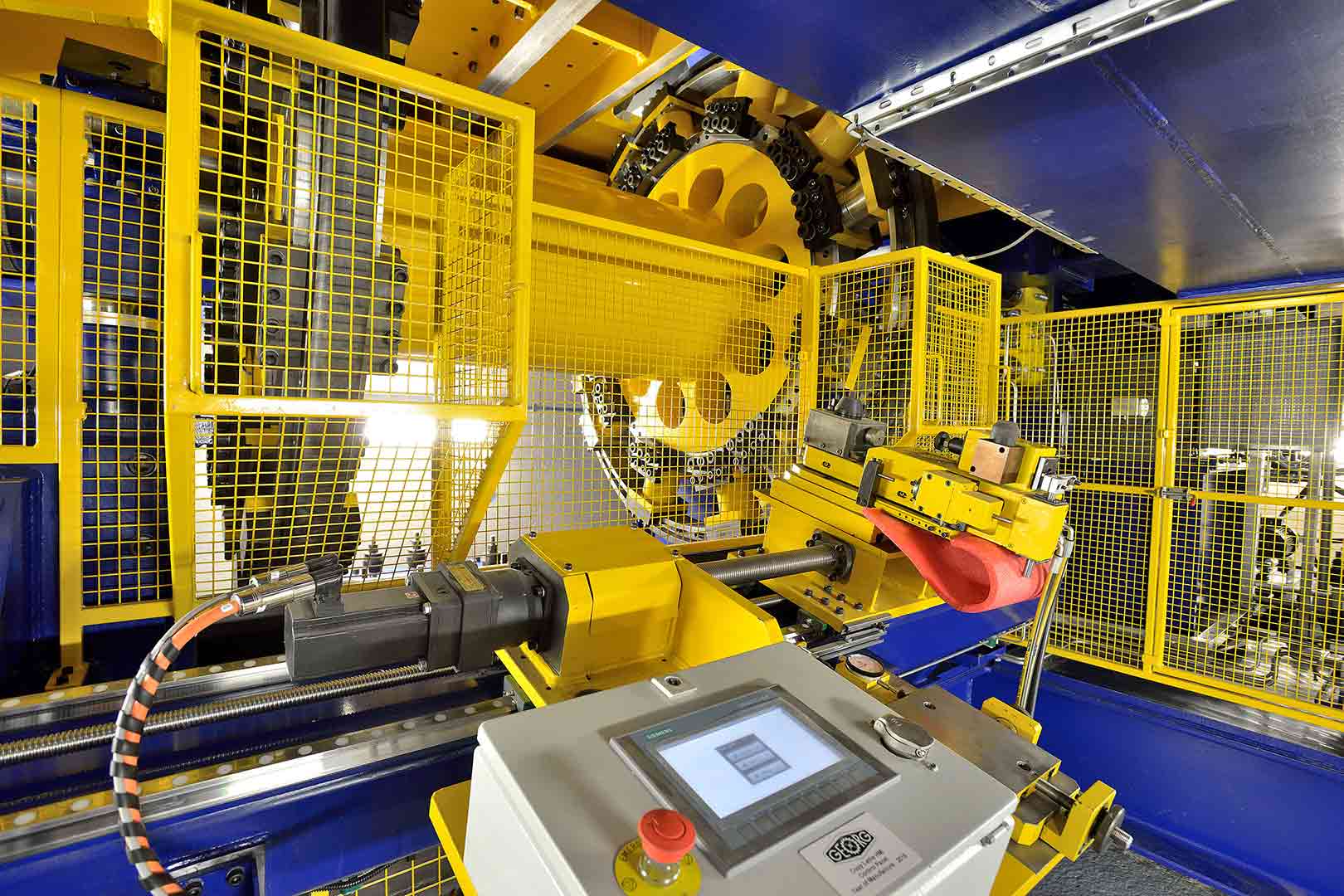
The HAROLD full-scale rolling contact, adhesion and braking rig is unique in combining a large 2m diameter rotating rail drum, with the capability to test a complete bogie assembly.
The rig is based around a rail drum with two circumferential rails, a bogie manipulation platform and a loading frame and actuators to allow body vertical and roll motions to be imposed through the bogie’s secondary suspension up to a maximum axle-load of 25t and running speed of 200kph.
The wheelset of the bogie under test is placed on the rail drum whilst the trailing axle is fixed to the manipulation platform. This facilitates both bogie rotation and lateral displacement relative to the rails, allowing the wheelset to be manipulated to represent various steady-state curving scenarios.
Wheelset position can also be controlled explicitly via attachment of actuators directly to the axle boxes of the test bogie. This functionality allows precise control of the lateral displacement and angle of attack of the wheelset, a key benefit when studying the details of wheel-rail interaction and contact mechanics.
The rig has the capacity to reach up to 110kNm of braking torque, this is sufficient for complete slip (wheel-slide) between wheel and rail at 25t axle-load. This allows adhesion and brake system performance (including WSP) to be investigated under realistic operating conditions. With an upgraded HAROLD 2.0 now under development, the study of traction system behaviour, dynamic braking (all-electric WSP), train brake blending strategies and hybrid drivetrain solutions will soon be added to the rig’s functionality (December 2021).
HAROLD is suitable for conducting research in a variety of areas including:
- Effect of wheel-rail contaminants on interface performance
- Wheel-rail friction modifier evaluation (top of rail or gauge face)
- Traction and braking/WSP performance optimisation
- Brake pad material development and change-out studies (duty cycles
- Novel wheel and rail material evaluation
- Composite and conventional vehicle component testing
- Accelerated fatigue testing
- Wheelset longitudinal suspension (yaw) measurement and optimisation for minimisation of steering forces
- Vertical bogie dynamics; optimisation of the primary and secondary suspension
- Analysis of novel wheelset and bogie technologies
- Noise and vibration analysis (wheel squeal)
- Assessment of existing (measured) wheel and rail profiles
- Identification of profile development areas (e.g. flange root/tread geometry) and trial of new profile shapes
- Assessment of ground/milled rail profile proposals
- Wheelset life estimation and extension
- Minimisation of contact forces – reductions in wear and RCF
- 125mph (200 kph) maximum speed
- 25t axle-load limit (50t applied vertical load)
- 110kNm braking torque reaction capability, 0.45MW (continuous power)
- Up to 3m bogie wheelbase and 10t maximum bogie weight
- Up to 6 degrees of bogie yaw relative to rollers
- Up to 20mm bogie lateral displacement relative to rollers
- Single 2m diameter rail drum minimises contact errors whilst maintaining cycle time benefits of a rolling rig
- Rail gauge 1435mm
- Inbuilt lathe which allows for any new or worn rail profile to be applied to the rail roller (EN 60E2 standard test profile)
- Rail roller in discrete sections to allow the representation of effects of rail bending and track support stiffness on damage modes
- Up to 4 rail material types in one revolution (4 segments)
- 128 analogue data channels at up to 10kHz sampling
- Precise wheel-rail creep control (resolution of <0.1% creep)
- 3-axis wheel/rail contact force measurement (both wheels)
- Hardware-in- the-loop control for evaluation of whole-train braking performance (under development)
- Applied load and displacement measurement
HAROLD: 50t Advanced Dynamic Test Cell
The IRR’s advanced dynamic test cell provides a high-load capacity facility for mechanical static and dynamic testing applications. With a 50t capacity loading system across a fully modular test floor of
10m x 4m, the rig can accommodate a wide range of test specimens and configurations.
With the support of IRR research staff, the test rig’s state-of-the-art hardware-in-the-loop control system can be used to design novel mechanical experiments which include elements of closed-loop dynamic co-simulation or measured load profile data extracted from the operating environment of the component under test.
Within the railway sector, the rig is perfectly suited to high-cycle fatigue testing of complete trackform systems (slab and ballast) and their components. From a vehicle perspective performance of suspension components and fatigue testing of bogie frames and associated equipment are within the capabilities of the facility. These are purely examples and we welcome test application proposals from any discipline of engineering.
The specification and typical railway applications of the 50t advanced dynamic test cell are detailed below:
The 50t Dynamic test cell is suitable for conducting research in a variety of areas including:
- Complete trackform testing and parameter optimisation (up to 10 sleeper bays)
- Rail pad testing (load and frequency response)
- Baseplate and rail fixing system structural evaluation
- Accelerated component fatigue life analysis
- Sleeper to ballast interface testing (vertical and lateral)
- Modular slab track testing
- Viscous and friction damper characterisation
- Primary and secondary spring characterisation
- Accelerated component fatigue life analysis
- Active damper development with vehicle dynamics in-the-loop
- Multi-application dynamic HiL experiments
- 10m x 4m, 50t capacity strong floor
- Traversing crossbeam and indexed flooring for versatile load areas and fixture
- 100 kW hydraulic capacity
- Example performance envelope; 12 Hz at 10 mm at 50t (for a single 50t cylinder, smaller cylinders will yield higher velocity performance)
- Configurable with the multi-actuator capability
- 128 analogue data channels at up to 10kHz sampling
- Labview based Hardware-in-the-loop (HiL) control for advanced test applications